Заземлення будинку є одним із ключових елементів електробезпеки, який захищає мешканців від ураження електричним струмом, а також убезпечує електричні прилади. У цій статті розглянемо, що таке заземлення, чому воно потрібне, як працює і як правильно його облаштувати в приватному будинку.
Що таке заземлення?
Заземлення — це система, яка з'єднує електричні пристрої або елементи будинку із землею через провідник, щоб відвести надлишкову електричну енергію в ґрунт у випадку короткого замикання, удару блискавкою, витоку струму, або інших несправностей електричного обладнання.

Як працює заземлення?
Коли виникає надлишкова напруга, струм через заземлювальний провідник прямує до заземлювача і розсіюється в землі. У сучасних системах заземлення часто працює разом із захисними автоматами ПЗВ — пристроями захисного відключення, які миттєво вимикають живлення при виявленні витоку струму.
Навіщо потрібне заземлення?
- Безпека людей. Якщо в електромережі стається збій (наприклад, пошкодження ізоляції), струм може потрапити на корпус приладу. Без заземлення людина, доторкнувшись до такого корпуса, може отримати смертельний удар струмом. Заземлення відводить цей струм у землю, мінімізуючи ризик.
- Захист електроприладів. Заземлення допомагає уникнути пошкодження електроприладів від стрибків напруги.
- Захист від статичної електрики. Заземлення відводить статичну електрику, яка може накопичуватися на корпусі приладів, запобігаючи їх пошкодженню.
- Заземлення грозовідводу (блискавкозахисту). Якщо є відповідне обладнання, забезпечує безпечне відведення струму блискавки в землю, запобігаючи пошкодженню будівель і обладнання.
- Відповідність нормам. У багатьох країнах, включно з Україною, облаштування заземлення є обов’язковим згідно з будівельними та електротехнічними нормами, наприклад ПУЕ — Правила улаштування електроустановок.
Інвертори та сонячні генератори обов’язково потрібно заземлювати для захисту від ураження струмом, перевантажень і пошкоджень через перенапругу. Зараз, коли через часті відключення електроенергії все більше людей використовують ці пристрої, питання правильного заземлення стає особливо актуальним для їхньої безпечної та надійної роботи.
Види заземлення
За типом заземлювача:
- Природне заземлення. Використовуються природні металеві конструкції, що знаходяться в землі: водопровідні труби, металеві фундаменти тощо.
- Штучне заземлення. Створюється спеціально шляхом встановлення металевих заземлювачів (стрижнів, смуг) у землю.
За системами заземлення:
- TN-S — особливість системи полягає в тому, що нейтральний провідник (N), який повертає струм до джерела живлення, і захисний провідник (PE), який слугує для заземлення і захисту від ураження струмом, повністю розділені на всьому шляху від трансформатора до кінцевого споживача. Найнадійніша і найбезпечніша.
- TN-C — система заземлення є простішою і менш безпечною порівняно з TN-S. У ній нейтральний (N) і захисний (PE) провідники об'єднані в один спільний провідник, який називається PEN (protective earth neutral), на всьому шляху від джерела живлення до споживача. TN-C часто використовувалася в старих будівлях і мережах, але зараз вважається застарілою і замінюється на новіші системи.
- TN-C-S — система заземлення є гібридом TN-C і TN-S. У ній від джерела живлення до певної точки (наприклад, вхідного щитка) нейтраль (N) і захисний провідник (PE) об'єднані в один PEN-провідник, як у TN-C. Далі, від цієї точки до споживача, PEN розділяється на окремий нейтральний (N) і захисний (PE) провідники, як у TN-S.
- IT — система заземлення характеризується тим, що нейтраль джерела живлення або ізольована, або заземлена через великий опір, а захисне заземлення (PE) споживача підключене до локального заземлювального контуру. Це забезпечує високу надійність: при першому замиканні на землю мережа продовжує працювати, а струм витоку мінімальний. Використовується в критичних об’єктах (лікарні, шахти), але потребує постійного моніторингу ізоляції та ПЗВ (пристроїв захисного відключення).
- TT — ця система заземлення відрізняється тим, що захисне заземлення (PE) споживача підключене до локального заземлювального контуру, незалежного від нейтралі (N) джерела живлення. Нейтраль (N) на стороні трансформатора заземлена окремо, а захисний провідник (PE) на стороні споживача з’єднується з власним заземленням, наприклад, заземлювальним стрижнем чи контуром. Часто використовується в приватних будинках, де неможливо використати заземлення від джерела живлення, але вимагає ретельного проєктування й обслуговування.
Для приватного будинку рекомендується використовувати систему TT або TN-S, залежно від місцевих умов і можливостей підключення.
Основні елементи заземлення
Заземлювальна система, наприклад TT складається з наступних компонентів:
- Заземлювача — металевих елементів (стрижнів, труб чи пластин), які закопуються в землю.
- Заземлювального провідника — кабелю, що з’єднує заземлювач із заземлювальною шиною, щитком або конкретним приладом.
- Контур заземлення – сукупність електродів (заземлювачів), розташованих у землі для кращого розподілу струму.
- Головної заземлювальної шини — точки, де всі заземлювальні проводи об’єднуються в будинку. Розташовується в ввідно-розподільному пристрої (ВРП).
- Грозозахист – додатковий елемент для відведення струму блискавки, складається з блискавкоприймача, струмовідводу (провідника до землі) та заземлювача.
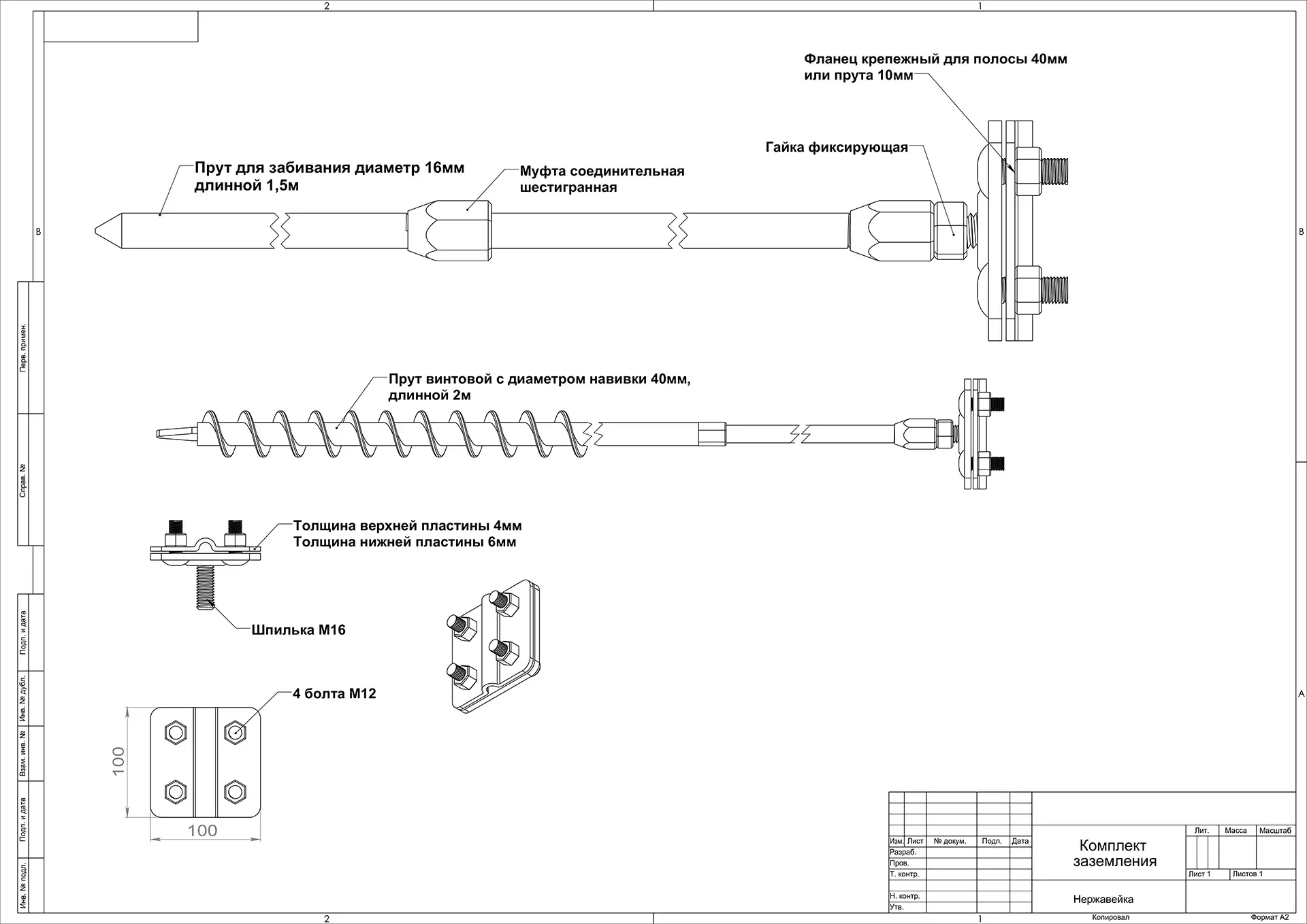
Заземлення приватного будинку площею 100–150 м²
Для сучасного приватного будинку площею 100–150 м² рекомендовані значення опору заземлення залежать від типу електропостачання та заземлювальної системи:
Норми опору заземлення
- Для системи TN-C-S (найпоширеніша в сучасних будинках) опір заземлення не повинен перевищувати 4 Ом. Це значення забезпечує безпечну роботу захисних пристроїв, таких як ПЗВ (пристрій захисного відключення), і відведення струму в разі аварії.
- Для системи TT, опір також рекомендується до 4 Ом, але може бути до 30 Ом, якщо встановлено ПЗВ із чутливістю 30 мА, що забезпечує захист від ураження струмом.
- Опір заземлення для блискавковідводу — не більше 10 Ом (згідно з ДСТУ Б В.2.5-38:2008). Якщо контур об’єднаний із захисним заземленням, орієнтуються на найсуворішу норму — 4 Ом.
Для промислових об'єктів опір заземлення залежить від класу електроустановок. Для електроустановок до 1000 В він не повинен перевищувати 4 Ом, для понад 1000 В – 0,5 Ом.
Чому 4 Ом?
- Це значення гарантує, що при короткому замиканні чи витоку струму автоматичні вимикачі або ПЗВ спрацюють швидко й ефективно.
- Чим нижчий опір заземлення (в Омах), тим швидше і ефективніше струм відводиться в землю.
- Для будинку 100–150 м² із сучасним обладнанням (електроплита, кондиціонери, електропідігрів підлоги, котел тощо) і потужністю 10–15 кВт це стандартне значення.
Як досягти 4 Ом?
Для будинку 100–150 м² зазвичай вистачає:
- 3–5 стрижнів (довжиною 2–3 м, діаметром 16–20 мм), забитих у формі трикутника чи лінії.
- З’єднання сталевою смугою 40х4 мм або мідним провідником, який найкраще проводить струм.
- Розташування в зволоженому місці (наприклад, біля водостоку).
- Якщо опір після монтажу перевищує 4 Ом, додають ще електроди або використовують хімічні підсилювачі провідності ґрунту.
Як облаштувати штучне заземлення в будинку?
Крок 1: Планування
- Визначте місце для заземлювача. Воно має бути вологим (але не підтоплюваним) і доступним для обслуговування. Подалі від доріжок та місць частого перебування людей.
- Перевірте тип ґрунту: піщаний ґрунт має вищий опір, ніж глинистий чи звичайний, тому може знадобитися більше заземлювачів.
Крок 2: Вибір матеріалів
- Заземлювач (електрод): Сталеві стрижні діаметром не менше 16 мм чи мідні пластини, або гвинтові палі. Довжина стрижнів — 2-3 метри.
- Провідник: Мідний кабель перетином не менше 10 мм².
- Кріплення: Пластини, шпильки, фіксувальні гайки, болти, хомути для надійного з’єднання.
Якщо ви не маєте досвіду в електромонтажі, краще звернутися до кваліфікованих спеціалістів. Також система заземлення має обов’язково бути перевірена і завірена спеціалістом з обленерго.
Крок 3: Монтаж
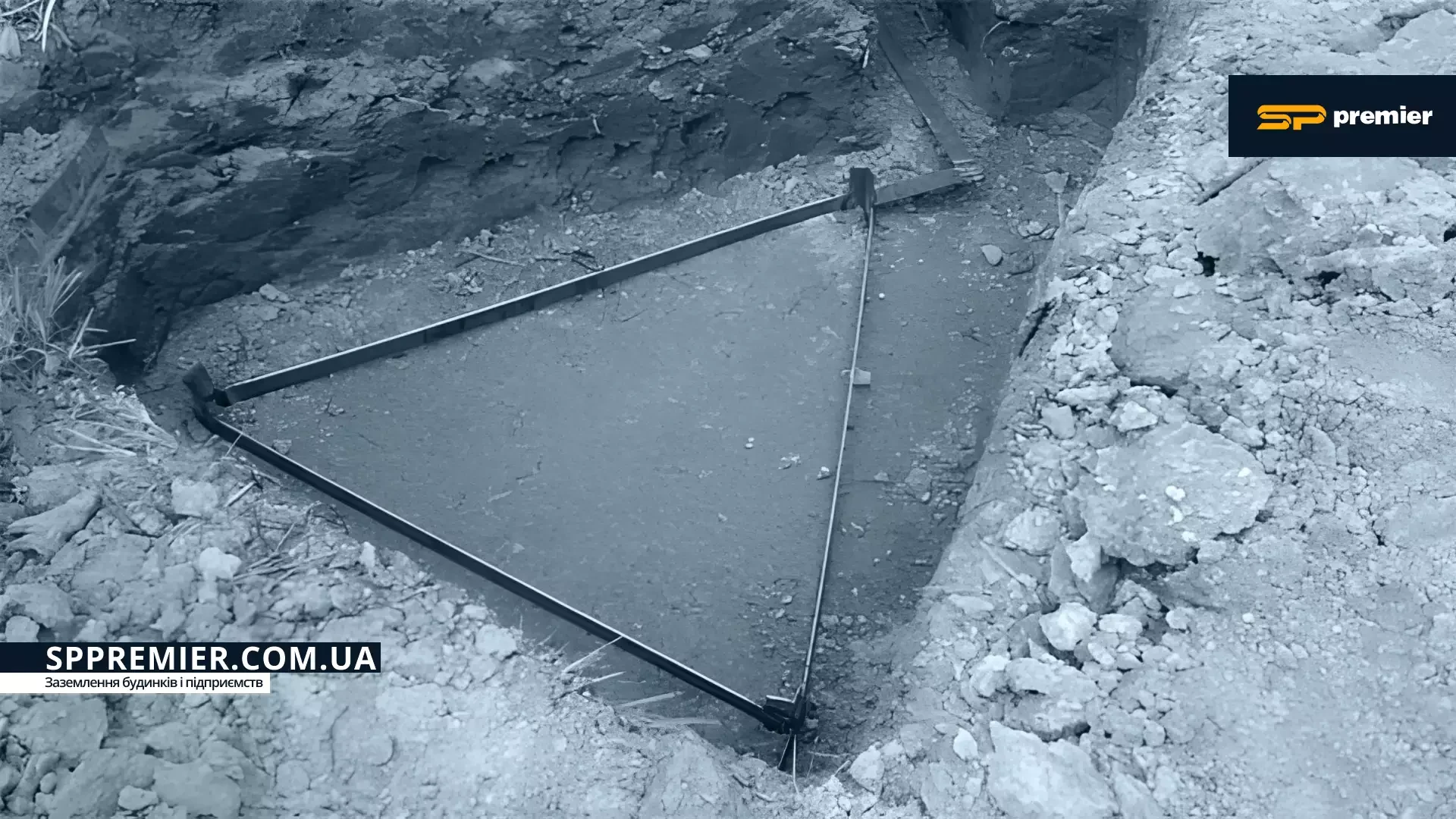
- Викопайте яму або траншею у формі трикутника глибиною 0,5-1 м.
- Забийте заземлювачі в землю на глибину не менше 2,5, розташувавши у формі трикутника з відстанню 1-2 м між ними.
- З’єднайте заземлювачі між собою металевим профілем зі зварюванням.
- Підключіть заземлювальний провідник до контуру і проведіть його до головного розподільного щита.
- У щиті підключіть провід до головної заземлювальної шини.
Крок 4: Перевірка
- Виміряйте опір заземлення спеціальним приладом (мегаомметром). Норма — до 4 Ом для побутових мереж.
- Переконайтеся, що система працює разом із ПЗВ.
Помилки заземлення
Помилки при встановленні заземлення можуть призводити до небезпечних ситуацій, таких як ураження струмом, пошкодження електроприладів, перегрівання чи навіть пожежі. Ось найпоширеніші помилки, пов'язані із заземленням:
- Неправильний вибір місця для заземлювача. Наприклад коли заземлювач встановлюють у сухому ґрунті з високим опором (наприклад, піску), що знижує ефективність заземлення. Щоб покращити ефективність заземлення в такому ґрунті, потрібна більш складна конструкція і довша глибина стрижнів.
- Неправильний вибір провідника заземлення. Використання дротів малого перерізу або матеріалів, що не відповідають вимогам (наприклад, алюмінію замість міді), може спричинити перегрів і вивести з ладу заземлення.
- Обрив або корозія заземлюючого провідника. Якщо заземлюючий провідник обірвався або зазнав сильної корозії, ефективність заземлення втрачається.
- Недостатня глибина або кількість заземлювачів. Якщо заземлювачі встановлені недостатньо глибоко або їхня кількість замала то опір заземлення може буде завеликим, а ефективність заземлення буде низькою, через це пристрої захисту можуть не спрацьовувати або спрацьовувати із затримкою.
- Використання невідповідних для заземлення конструкцій. Старої арматури фундаменту, труб або інших металевих конструкцій без перевірки їхньої електричної безперервності може призвести до неефективного заземлення або навіть до небезпечних ситуацій.
- Поганий контакт між елементами. Окислення, погане затискання болтів або пайки можуть збільшити опір контакту, що може спричинити перегрів і вихід заземлення з ладу.
- Неправильне підключення заземлюючих контурів може призвести до пошкодження обладнання та порушення роботи електромережі, або становити небезпеку для життя людей. Тому необхідно дотримуватися вимог «Правил улаштування електроустановок».
Заземлення будинку — це не просто технічна формальність, а життєво важлива система, яка забезпечує безпеку та комфорт. Правильно спроєктоване і встановлене заземлення може врятувати життя і захистити майно від аварій, а весь будинок — від пожежі. Якщо ви будуєте чи модернізуєте свій дім, не ігноруйте цей етап — вкладення в безпеку завжди окупаються.
Якщо вам потрібне надійне та безпечне заземлення, звертайтеся до SP Pemier! Пропонуємо якісне проєктування та встановлення заземлення для будинків, підприємств і промислових об’єктів, гарантуючи відповідність усім нормам та вимогам безпеки. Зв’яжіться з нами, щоб отримати консультацію та замовити монтаж заземлення!
Замовити послугу монтажу заземлення:
Телефон: +38 050 431-70-60
Viber: +38 050 431-70-60
WhatsApp: +38 050 431-70-60
Telegram: +38 050 431-70-60
Електронна пошта: info@sppremier.com