- The four numbers that make up the calculation
- Step 1. Pile length
- Step 2. Diameter and series: selecting by load
- Step 3. Spacing between piles
- Step 4. Number of piles: layout along the perimeter
- What changes the calculation: soil
- How to install: three methods and the limits of each
- Mistakes we most often see in other people's calculations
- Questions from customers
A pile foundation is calculated from four numbers: length, diameter, spacing and quantity. Length depends on the soil frost depth and the pile parameters, diameter on the load per support, spacing on the stiffness of the frame (no more than 3 m), and quantity on the layout along the perimeter. A mistake in any of these numbers costs you either extra piles in the estimate or a sagging structure two seasons later.
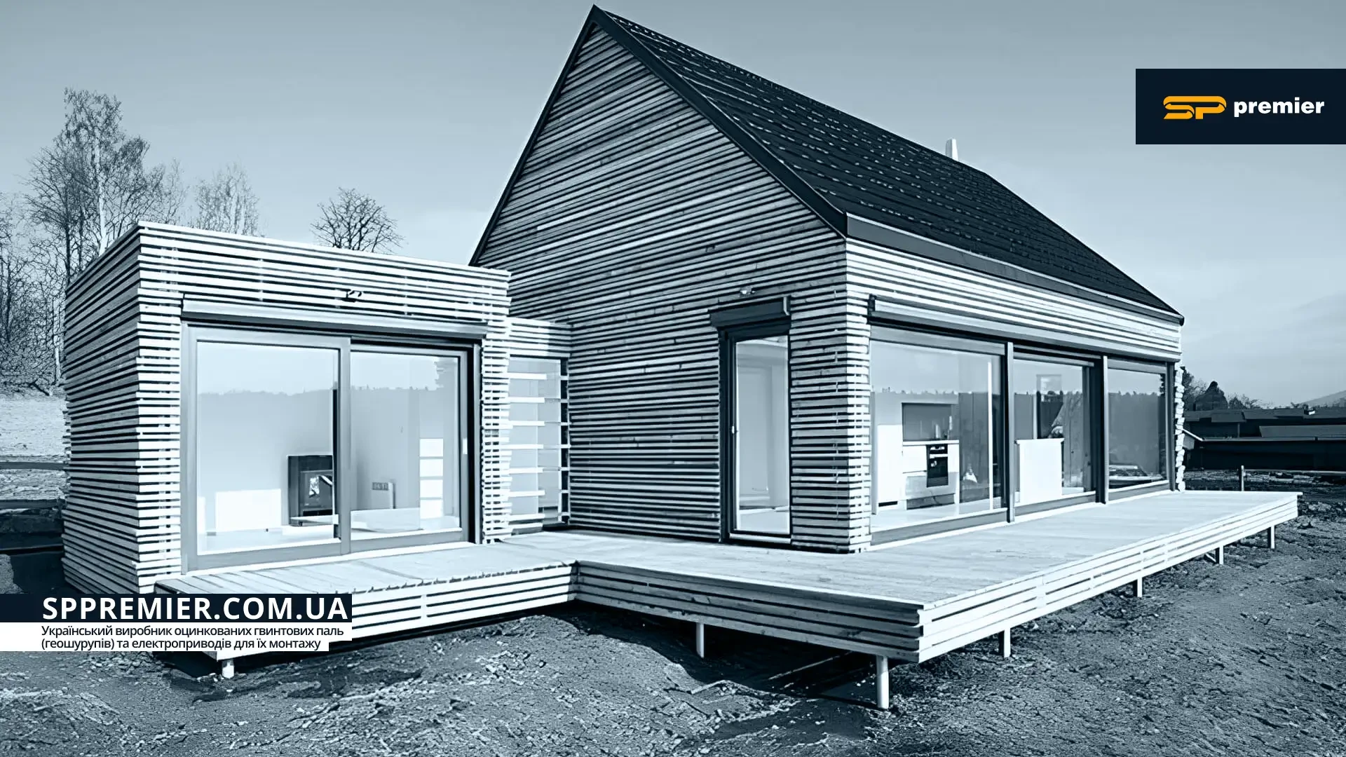
Timber-frame house with a terrace on a ground screw pile foundation
The four numbers that make up the calculation
A pile field is calculated in a fixed order, and it is not worth changing it. Length depends on soil and climate, diameter on the load, spacing on the stiffness of the frame, and quantity on the first three.
At SP Premier we always start with the geometry of the structure: the customer provides the exact dimensions, the number of storeys, the wall material and the type of frame. Without this data any figure is a guess. Then we calculate in this order:
- Pile length L1 — so that the helix sits below the frost depth.
- Diameter and series — so that the bearing capacity exceeds the load per support.
- Spacing between piles — so that the frame does not sag between supports.
- Number of piles — the result of the layout along the perimeter and at load points.
Step 1. Pile length
A ground screw pile carries the load not with the pipe wall but with the helix resting on compacted soil. So the whole logic of the length calculation comes down to one thing: the helix must be entirely below the layer that freezes and heaves every winter.
Pile length is calculated with the formula: L1 = A + L2 + H
In SP Premier pile markings this calculation is built right into the product designation: SPGS F D×T×L1(L2), where
- D — pile diameter, mm;
- T — pile wall thickness, mm;
- L1 — pile length, mm;
- L2 — length of the helix, mm.
For example: ground screw pile SPGS F 76x3x1500(500).
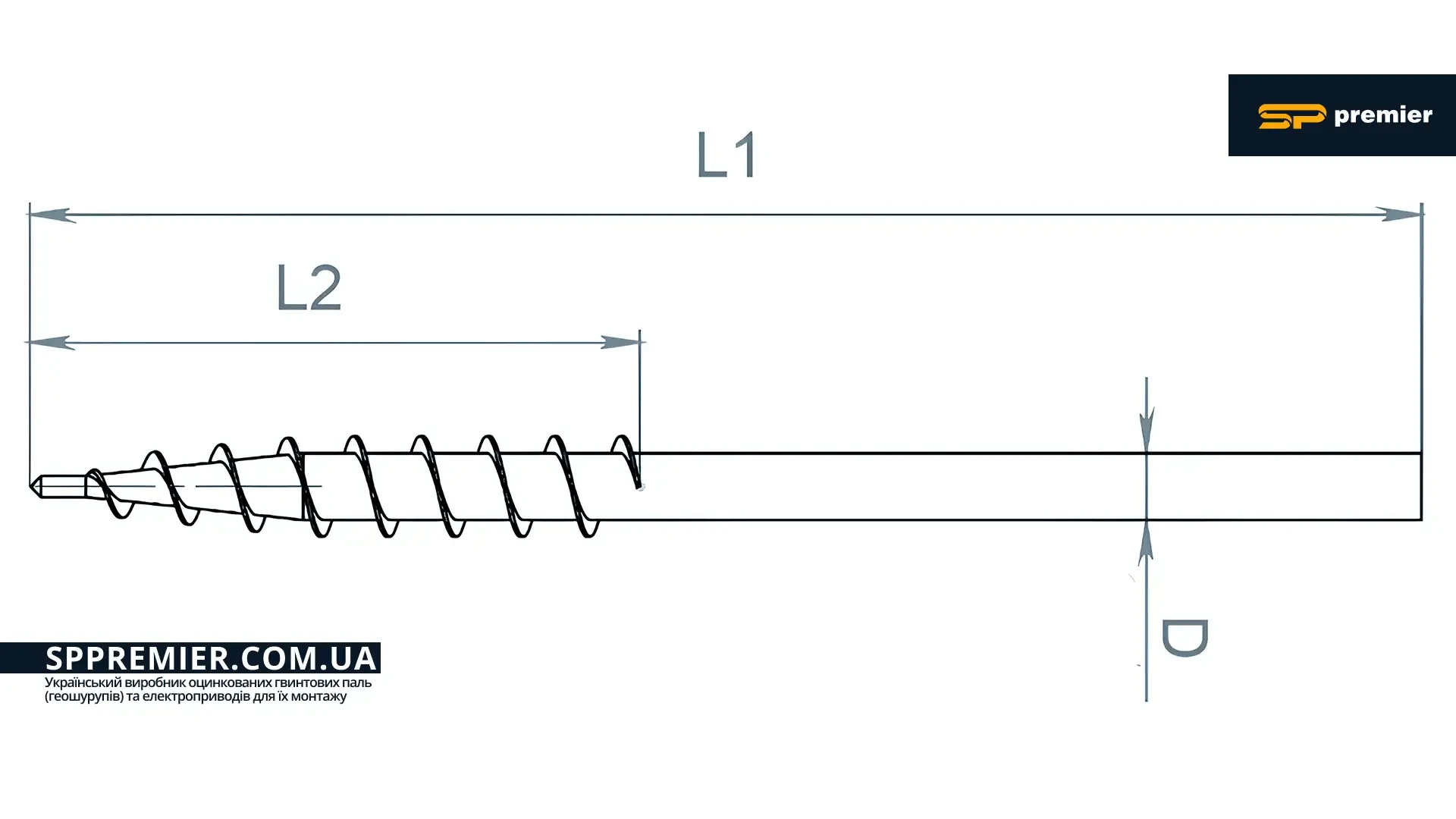
Ground screw pile drawing: L1 — pile length, L2 — helix length, D — pipe diameter, helix pitch 48 mm
A — soil frost depth
This is a standard value, not the depth you saw last winter. It is taken from DBN (the State Building Codes of Ukraine) for the specific locality, and it differs between regions of Ukraine: roughly from 0.5 m in the south and in Zakarpattia to 1.1–1.2 m in the east. For Kyiv and the Kyiv region the approximate value is close to 0.9 m. Take the exact figure for your site from the codes, not the national average: a difference of 30 cm means a difference in pile length and in the price of the whole foundation.
L2 — helix length
This is the working part of the pile, the very blade that compacts the soil and transfers the load to it. In our standard models L2 is 350 or 500 mm, and this figure is given in brackets in the marking. It is added to the frost depth, not included in it: the helix must be entirely below the frozen layer.
H — flange height above ground level
This is what remains above the surface for the frame. The value is set by the project: plinth height, the slope of the site, and a margin for levelling the piles. For a terrace 150–300 mm is usually enough; for a house on a slope this figure can be several times higher.
Length calculation example
A terrace in the Kyiv region, pile SPGS F 60x3x2000(650), plinth 300 mm:
- A = 900 mm (approximate standard frost depth);
- L2 = 650 mm (helix length of this model);
- H = 300 mm (flange height above ground);
- L1 = 900 + 650 + 300 = 1850 mm.
Piles up to 1700 mm long are not suitable for such a structure: the helix would end up above the frost depth. Our piles are made from 1.2 to 6 m long, so the SPGS F 60x3x2000(650) size fits.
The most common beginner's mistake is to calculate the length as "frost depth plus a margin". L2 is forgotten, and the helix stays in the layer that moves every winter.
Step 2. Diameter and series: selecting by load
The pipe diameter determines how much load one support can carry. Our ground screw piles are made of ST3 steel with hot-dip galvanizing to DIN EN ISO 1461, with a narrow-blade multi-turn helix: blade 3 × 16 mm, helix pitch 48 mm.
The SP Premier standard range includes three series that differ in the pile head:
- SPGS N — without a flange, for a separate pile cap;
- SPGS F — with a hexagonal flange;
- SPGS U — with a U-shaped flange.
The flange is chosen not by taste but by the connection detail. A hexagonal flange suits a steel frame and plate; a U-shaped one suits a timber beam or joist that sits inside the profile. A flangeless pile is needed where the cap is selected separately for a non-standard connection.
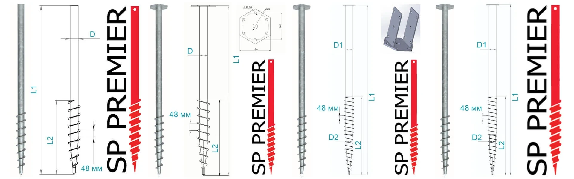
SP Premier ground screw piles: without a flange, with a hexagonal and with a U-shaped flange
Bearing capacity of standard models
The figures below are average values for one soil type, in tonnes. Compression shows how much the pile carries under compression, uplift — under pull-out, which is critical for fences, canopies and any structures exposed to wind.
| Model | Compression, t | Uplift, t |
|---|---|---|
|
0.400 |
0.300 |
|
|
0.610 |
0.460 |
|
|
1.380 |
0.760 |
|
|
2.500 |
1.270 |
How to match the load to the diameter
The logic is simple: the total load is divided by the number of supports, and the resulting load per pile must be lower than the table compression value with a margin. In our calculations we allow a 25–30% margin. This is our internal practice, not a standard.
What goes into the total load:
- dead load of the structure — frame, beams, roof, floor, wall infill;
- live load — people, furniture, equipment, machinery;
- snow load — according to DBN V.1.2-2:2006 for your region;
- wind load — uplift is calculated separately for canopies and fences.
For a fence and sliding gates the wind component often turns out to be decisive. A solid 2 m high corrugated sheet leaf works like a sail: the pile receives not so much weight as a moment trying to twist it out. That is exactly why the table has an "uplift" column, and it is the one to look at first when calculating a fence.
For a terrace, calculate compression. For a fence, canopy or gate — uplift. These are different numbers and often different diameters.
Step 3. Spacing between piles
Spacing is the centre-to-centre distance between neighbouring supports. It depends not on the pile but on the stiffness of what rests on it: a timber joist, a steel channel, a grillage beam.
At SP Premier we work on the basis that piles are screwed in no more than three metres apart. This is the upper limit, not a default recommendation. The real spacing is usually smaller:
| Structure type | Spacing between piles |
|---|---|
|
Light garden structure with a timber frame |
1.5–2 m |
|
Terrace, gazebo, canopy |
2–2.5 m |
|
Frame or modular building |
According to the joist layout, usually 2–3 m |
|
Heavy point loads |
A separate pile regardless of spacing |
Regardless of spacing, a pile is always placed:
- At every corner of the perimeter.
- At the intersections of load-bearing walls and partitions.
- Under point loads — columns, roof supports, a stove, a barbecue, stairs.
- At frame joints, if the beam is not continuous.
Increasing the spacing beyond 3 m to save two or three piles is the most expensive saving in this calculation. The frame starts working in bending, the floor becomes springy over time, and the connections loosen.
Step 4. Number of piles: layout along the perimeter
The number is not chosen, it is derived. First the perimeter is drawn on the plan, then the mandatory points from the list above are placed, then the spans are filled with the chosen spacing.
Example: a 4 × 6 m terrace
With a 2 m spacing there are 4 points along the long side (0, 2, 4, 6 m) and 3 points along the short side (0, 2, 4 m).
- Perimeter: 2 × 4 + 2 × 3 − 4 corners = 10 piles
- Middle row along the 6 m side: +2 piles
- Total: 12 piles
The middle row is needed if the joists span 4 m without an intermediate support. If the frame allows such a span, it is not needed and the foundation will take 10 supports.
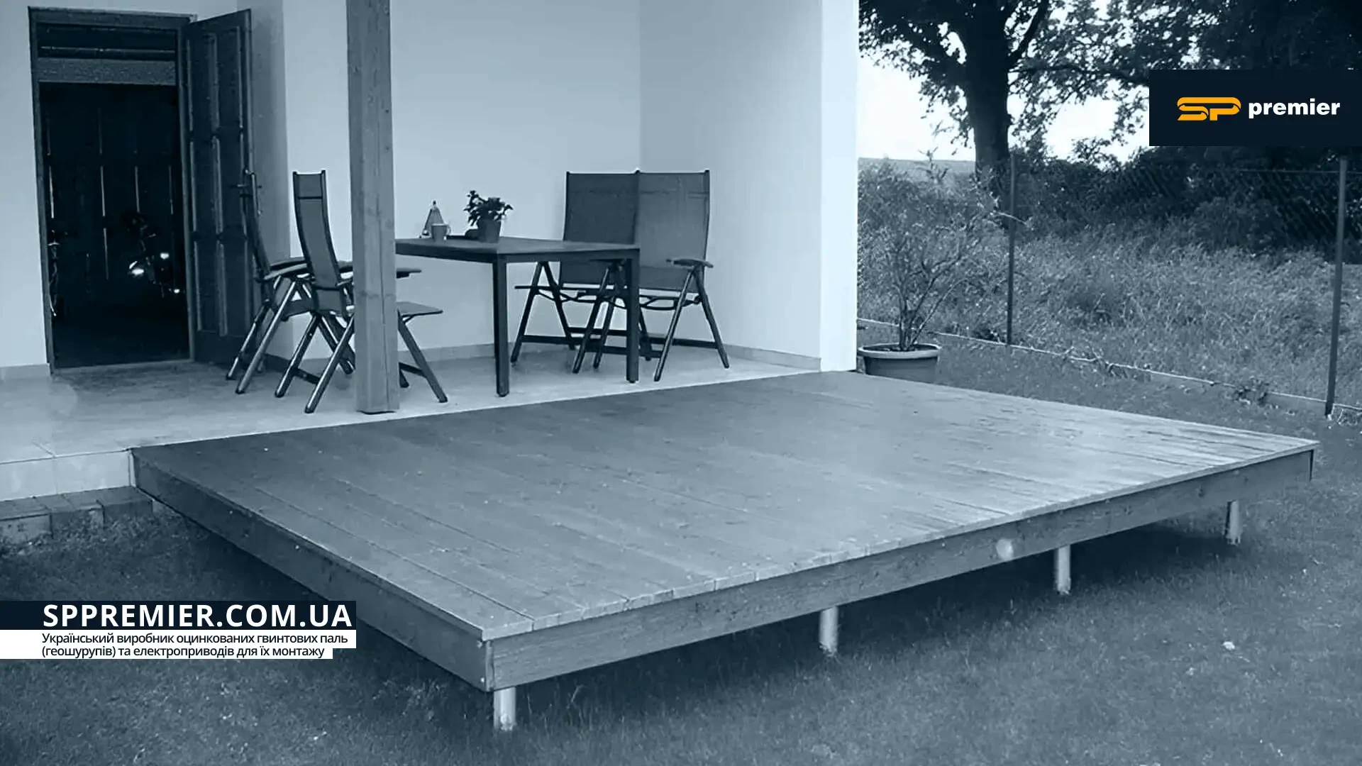
Timber terrace on ground screw piles: supports at the corners and along the perimeter at an even spacing
Example: a 3 × 3 m gazebo
With a 1.5 m spacing there are 3 points on each side.
- Perimeter: 2 × 3 + 2 × 3 − 4 corners = 8 piles
- A separate support for a barbecue or stove: +1 pile
Example: a 30-metre fence
Here it is not the perimeter that is counted but the spans between posts. With a 2.5 m spacing that gives 12 spans and 13 piles. Corner and gate posts are calculated separately: they additionally carry the moment from the leaf and the weight of the gate.
What changes the calculation: soil
The table values of bearing capacity apply to soils in which a ground screw pile works as intended. Our piles may be used on sites with the following soils:
- loams;
- water-saturated clays;
- sandy loams;
- silty and fine sands;
- sites with a very high groundwater level.
They are not recommended in two cases:
- stony soils;
- soils containing construction debris.
The reason is the same in both cases: the helix either will not pass or will be deformed, and a deformed helix no longer provides the design compaction. The resistance during screwing works here as an indirect indicator of soil density: if the pile goes in too easily at the design depth or, on the contrary, suddenly stops, the calculation for that point is reviewed.
How to install: three methods and the limits of each
The installation method does not change the design numbers, but it does change which size you can physically install on your site.
By hand. After marking out, a vertical pilot hole is made in the ground, no wider than the pile diameter and as deep as the soil allows. An adapter is attached to the flange and lever pipes are inserted into it. The method works for small diameters and shallow depths.
With an electric driver. Our SP GS 1800 electric ground screw driver delivers 500–1800 N·m of torque at 1800 W and a rotation speed of 8 rpm. It is designed for piles 42, 60 and 76 mm in diameter and up to 1500 mm long. The driver weighs 9.2 kg and needs 2–3 people to operate. This is the option for sites that machinery cannot reach: between houses, deep in a landscaped plot, on slopes and on the banks of water bodies. More about working with the electric driver in the article "Electric ground screw driver: saving time and resources".

SP Premier hand-held electric driver for screwing in piles without special machinery
With special machinery. Ground screw pile installation with hydraulic rigs mounted on BOBCAT and AVANT loaders where there is access. Faster, with larger diameters and depths.
Two rules apply to all three methods. The pile must not deviate from the vertical by more than two degrees, and this is checked throughout the screwing. And piles must never be driven: an impact deforms the helix, after which the design bearing capacity no longer applies.
Mistakes we most often see in other people's calculations
- Length is calculated without L2, so the helix stays in the frost layer.
- The frost depth is taken "as the neighbours did" instead of the standard value for the region.
- One diameter for the whole structure, although a heavy column or stove needs a separate support of a larger size.
- For a fence, compression is calculated and uplift is ignored.
- Spacing over 3 m "to save money", which makes the frame sag.
- H is not allowed for, and the flange ends up flush with the ground with no margin for levelling.
- The pile is forced further when it has stopped, instead of reconsidering the point or the size.
Questions from customers
Can I calculate the piles myself, without a soil survey?
For a light garden structure, yes, following the sequence above. For a residential house the calculation is made for the specific building: we take the geometry of the structure from the customer and calculate length, diameter and spacing individually.
Why are there two numbers for each model in the table?
Compression is the capacity under pushing down, uplift under pulling out. For a terrace the first matters most, for a fence or canopy — the second.
Can a pile be screwed in deeper than calculated?
Yes, and this is normal if the resistance at the design depth is low. A pile shorter than calculated is unacceptable; a longer one only affects the budget.
Does winter change the calculation?
It does not change the numbers. Frozen ground affects the installation technique, but the frost depth in the formula is a standard value that already accounts for the winter season. More in the article "Can screw piles be installed in winter?".
Contact us to calculate your foundation and order SP Premier ground screw piles!
Phone: +38 050 431-70-60
Viber: +38 050 431-70-60
WhatsApp: +38 050 431-70-60
Telegram: +38 050 431-70-60
E-mail: info@sppremier.com

